
I was recently given the awesome opportunity to play with a ZyXEL DSLAM by marrold of CuTEL in order to document my experience and configurations for use in the field as part of CuTEL’s services at EMF Camp.
I’ve wanted to play with a DSLAM for quite a while now. Ever since I was young, my boot sale and other second hand searches always turned up decent looking routers and modems (for example a few Drayteks and some cool looking old school BT kit) however they were sadly all doomed to obsolescence for anything more than a simple DHCP server and a switch as they all had DSL WANs with no alternative Ethernet WAN.
None of these devices need be completely useless however, as a Central Office end device for DSL is all you really need to bring service back to them! Sadly though, these rarely come up for sale after being decommissioned, and when they do they’re very (£200-500+) expensive, likely due to existing services needing replacement units making them desirable or simply because of the carrier grade aura around them. As such, I haven’t got my own unit, so was very glad for the opportunity to play with this one.
This post will probably change over time as new information is discovered, but the main purpose is to get example configurations out there and accessible so this DSLAM (and others like it) can be configured and put into service much like CuTEL is doing, within labs and hacker communities by anyone with a basic understanding of general networking and PPPoE.
What is this DSLAM?
Under the hood, the ZyXEL VES1724-55C is essentially a 24 port 100Mbps managed Ethernet switch with 2 Gigabit uplinks (exposed on the front of the chassis as ports 25 and 26) and a separate 100Mbps management port also exposed on the front of the chassis which cannot be used for DSL service.
In addition to your standard managed Ethernet switch functions like 802.1Q VLANs, port based VLANs, MAC VLANs, Link Aggregation, Mirroring etc, this switch also provides some DSL specific services for ADSL CPEs such as VPI/VCI mapping to VLANs, protocol de-encapsulation (LLC/SNAP & VC MUX), basic packet manipulation (removal or passthrough of Ethernet FCS bytes) and PPPoA to PPPoE adaptation for compatibility.
There’s also configuration for the CO side DSL modems in the DSLAM too, such as the VDSL encapsulation type, SNR alarms and compensation, TX power control and frequency band management such as enabling/disabling extended bands and RF notching for mitigating RFI problems.
This is only a very basic overview of the functions available, please see the manual for more information about functions not discussed in this post.
Main Goals
- Get VDSL working
- Build a few profiles for both VDSL and ADSL which range from high performance to high compatibility
- Get ADSL working
- Implement VLANs across the line
- Get a dual stack service running
- Exploring SNMP
Configuring VDSL
This DSLAM is intended for VDSL as its primary service. It requires some minimal setup before VDSL modems are able to connect, but from a factory reset device you’ll be able to get a VDSL service running in under 10 minutes.
Generic VDSL Configuration Example
This configuration works for establishing an VDSL connection over which PPPoE successfully connects and network access is achieved:
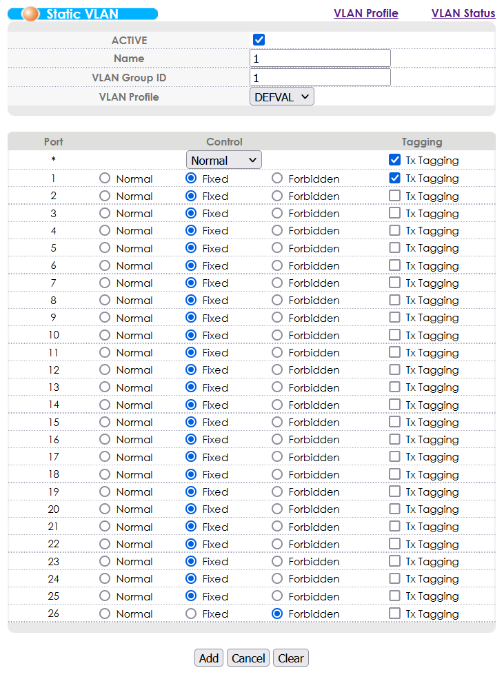
Assuming we’re using VLAN 1, enable VLAN TX Tagging for VLAN 1 on the DSLAM port to which the VDSL modem is connected.
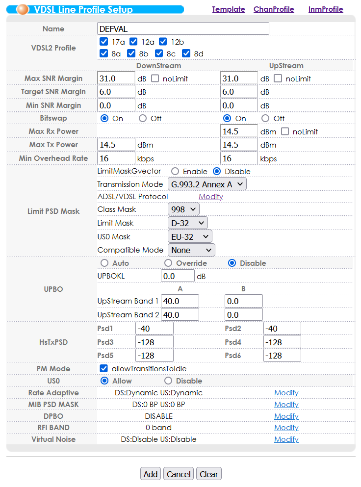
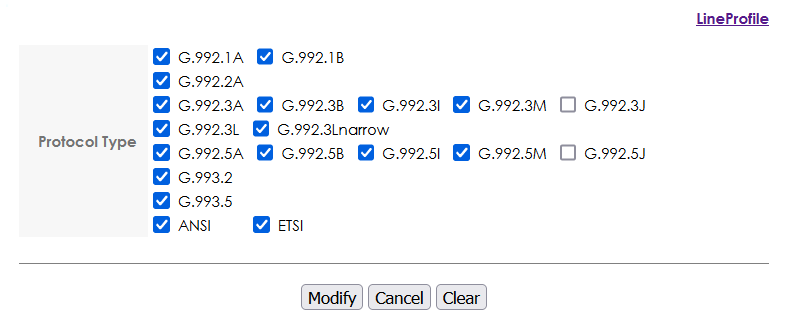
In the VDSL line profile setup, enable most xDSL protocols using the “Modify” link in the “Limit PSD Mask” section. You will need to click “Modify” after ticking all the boxes, then you will also need to click “Add” to save the current profile otherwise the boxes you ticket will become undone.
Configuring ADSL
Whilst this DSLAM is capable of ADSL, it definitely isn’t configured for it out of the box, and can require some fiddling to get working. I’ve done all of the legwork for you though, so as long as your ADSL modem is pretty standard and you follow the configuration examples closely, you’ll also be able to get an ADSL service running in about 10-15 minutes.
This DSLAM considers ADSL service a “fallback” service and has to be specially configured on a per-port basis in order to work. There isn’t too much you’ll need to do to get this working, but a misconfiguration will lead to broken Ethernet packets, weird Ethernet packets (PPPoA), or no connection at all, and there is not a lot of debug information that you can gather other than using the built in Port Mirroring function attached to a Wireshark instance to assess what kind of packets (if any) your modem is sending over the line.
Usefully, if ADSL Fallback is configured on a port it does not interfere with VDSL service on that port. This means you can preconfigure all ports with sane defaults from the very beginning even if you do not know which type of CPE will be connected on the other end.
Generic ADSL Configuration Example
This configuration works for establishing an ADSL connection over which PPPoE successfully connects and network access is achieved:
Assuming we’re using VLAN 1, enable VLAN TX Tagging for VLAN 1 on the DSLAM port to which the ADSL modem is connected.
In the VDSL line profile setup, enable most xDSL protocols using the “Modify” link in the “Limit PSD Mask” section. You will need to click “Modify” after ticking all the boxes, then you will also need to click “Add” to save the current profile otherwise the boxes you ticket will become undone.
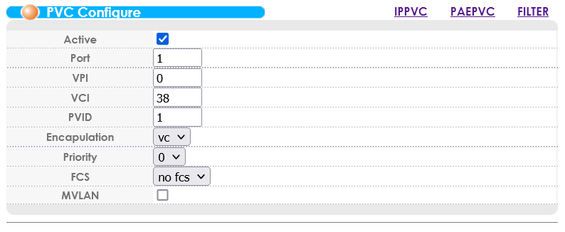
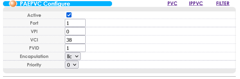
In the ADSL Fallback PVC configuration, create a PVC on the DSLAM port to which the ADSL modem is connected.
- VPI: 0*
- VCI: 38*
- PVID: set to the VLAN we configured earlier (1 in our example)
- Encapsulation: VC**
- FCS: No fcs (seems to chop 4 bytes off of all packets)
*Some modems allow you to choose the VPI/VCI. For the UK, the standard is to use 0/38, but in the scenario where your modem is fixed to a different value you’ll need to change these values on the DSLAM end to match the modem. Where possible, stick to 0/38 and update this on the modem end for consistency’s sake.
**If your modem is fixed to LLC/SNAP mode then you’ll need to change from VC MUX mode to LLC mode, but the default for PPPoE seems to be VC MUX.
If your ADSL modem doesn’t support PPPoE and requires the use of PPPoA, the DSLAM is capable of proxying PPPoA connections to your PPPoE device. This works almost the same as an ADSL Fallback PVC configuration, except that you want to create a PEAPVC, which you may have spotted in the PVC screenshot above. Below is a screenshot of a working PEAPVC configuration:
Performance and Compatibility Profiles
Having played around with the profiles, I have found that the modems are very good at selecting which protocols they want to use in order to achieve the best performance results. For forcing the best performance, it seems a good idea to keep G.993.2 and G.993.5 turned on only, but this is usually unnecessary and just enabling all of the possible profile results in a modem trying its best performance mode and dropping down if it is really necessary.
The “VDSL2 Profile” section at the top of the “VDSL Line Profile Setup” configuration page is used to select which bands in the VDSL2 bandplan are used for this profile. This can be especially useful in scenarios where one or more bands are causing interference, however turning any of these off will knock out a band and thus knock off performance from the connection.
Whilst I was here, I grabbed my SDR and hooked up a small antenna, placed near the DSL line between the DSLAM and VDSL CPE. Here are a few screenshots showing the VDSL bands:
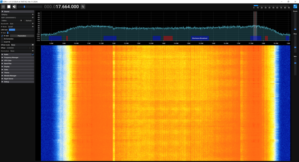

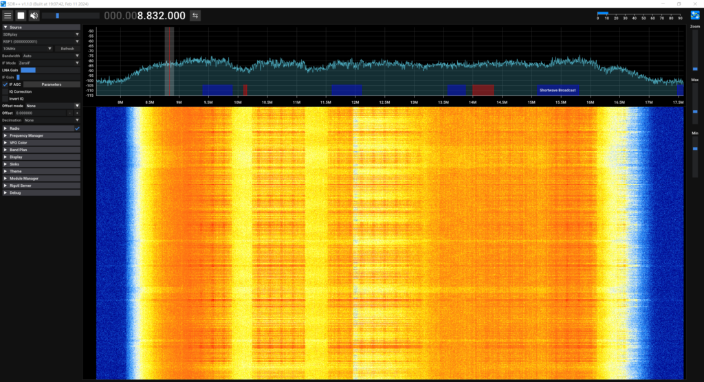
These are nowhere near the best screenshots but they give you a rough idea of the bands.
VLANs Across the Line
PPP is only capable of encapsulating Layer 3 packets, and therefore it is not possible to have multiple VLANs going over an established PPPoE tunnel, however it is possible to have VLAN tagged traffic a layer before the PPPoE connection is established.
Since the DSL connection to the DSLAM is just an Ethernet connection, you can run as many VLANs as you like directly over the DSL line. This means you could theoretically host multiple services with a mix of PPPoE, bridged networking or even just Layer 2 packets, segregated by VLANs which can be adjusted in the DSLAM’s switch configuration.
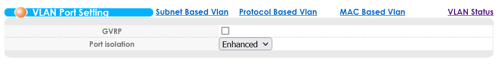
VLANs for Isolation? That can be handled differently!
If you’re looking to implement a bunch of VLANs in order to isolate the DSL CPEs from each other, you probably should be using the Port Isolation feature instead. This can be found alongside the VLAN Port Setting menu:
Getting a Dual Stack Service Running
We now have the basics of connectivity in place. Our DSL modems are able to establish a packet connection over our DSLAM to a device on one or both of the uplink ports so we now need to actually provide a service that the modems can connect to.
Where possible, using PPPoE is preferred as this can be directly be passed to the device on the uplink port and the session can be entirely handled by that device and the modems, however it is possible to use the PEAPVC option when configuring an ADSL PVC which will automatically handle the conversion between PPPoA being received from a modem to PPPoE to be sent to the device on the uplink port (discussed in the ADSL section).
It is also possible to configure modems to directly bridge traffic from DSL to an Ethernet port, which will allow another device to establish the PPPoE connection, or even to just allow a standard network to be accessed over DSL without any session management as if you were just plugging into any old network switch.
For the purposes of this guide, I am using a Mikrotik router plugged into one of the uplink ports, configured as a IPv4 and IPv6 DHCP server, with CGNAT for IPv4 and standard Prefix Delegation for IPv6:
# +-----------------------------+
# | Configure IPv4 Connectivity |
# +-----------------------------+

# Define a DHCP client to receive a public IP address
/ip dhcp-client
add interface=ether1

# Add a NAT Masquerade rule to allow routing to the internet via the public interface
/ip firewall nat
add action=masquerade chain=srcnat out-interface=ether1

# Add an IPv4 pool in the 100.64.0.0/16 range (Some of the CGNAT range as defined by RFC 6598)
/ip pool
add name=cgnat ranges=100.64.0.2-100.64.254.254

# +-----------------------------+
# | Configure IPv6 Connectivity |
# +-----------------------------+

# Add a DHCPv6 client which requests an IPv6 prefix used later for delegation to downstream clients
/ipv6 dhcp-client
add add-default-route=yes interface=ether1 pool-name=wanpd request=prefix

# +------------------------+
# | Configure PPPoE Server |
# +------------------------+

# Update the default PPP profile to delegate /64 IPv6 prefixes and IPv4 addresses from the pools to downstream clients, using 100.64.0.1 as the local CGNAT address
/ppp profile
set *0 dhcpv6-pd-pool=wanpd local-address=100.64.0.1 remote-address=cgnat

# Create the PPPoE server on a single interface (could be a bridge)
/interface pppoe-server server
add disabled=no interface=ether2 service-name=dsl

# Create an account a CPE can log in with
/ppp secret
add name=dsl password=a1b2c3
Exploring SNMP
I’m not particularly experienced with SNMP at all, however I do have the MIB for this device and can provide a quick demonstration of the data structure the DSLAM offers:
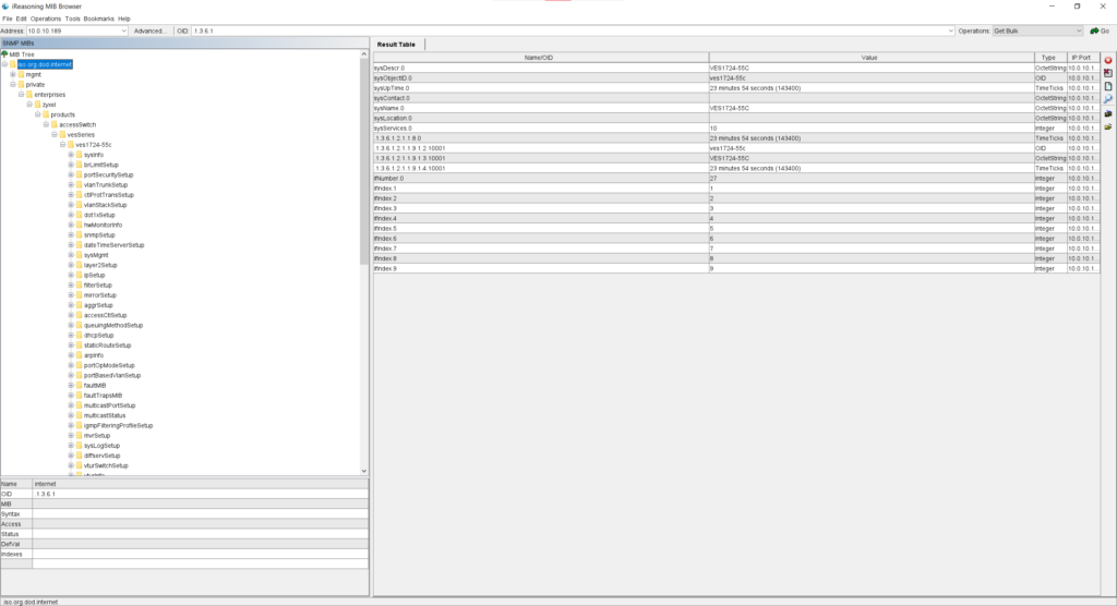
You can download the MIB file for the DSLAM below. For those curious, the software being used in the above screenshot is IReasoning MIB Browser Personal Edition, downloadable from https://www.ireasoning.com/downloadmibbrowserfree.php .